Anti-Reflection Coating Design: Single Layer, BBAR, and V-Coats
What single-layer MgF2, broadband multilayer and V-coat designs actually deliver, and the six items a coating drawing needs to match the delivered part to the design.
Anti-reflection coatings are usually the last item added to a lens drawing and the first item to limit yield. The reason is structural: an AR requirement is a spectral requirement, and a spectral requirement only means something when the band, the angle of incidence and the acceptance metric are all stated. This note explains what the three common coating families actually deliver, and how to specify them so that the coating you receive matches the coating you designed around.
Why uncoated glass costs about 8%
At normal incidence, a bare BK7 surface reflects roughly 4% per interface, so a simple singlet loses about 8% of the signal before any absorption or scatter is counted. In a multi-element assembly the loss compounds and, worse, the reflected light becomes ghosting and flare rather than disappearing. Anti-reflection coatings work by creating a controlled interference condition at the surface, and the number of layers determines how wide a band and how low a reflectance they can hold.
Single-layer MgF2: the narrow-band workhorse
A quarter-wave magnesium fluoride layer has an index of about 1.38, which sits between air and BK7 and produces a minimum reflectance in the region of 1.3% per surface at the design wavelength. It is durable, laser-damage tolerant and inexpensive, and it is the correct answer for narrow-band systems — a 632.8 nm interferometer, a single-line laser, a monochrome illumination path. Outside its design band the reflectance climbs quickly, so a MgF2-coated window specified for "visible" will show visibly higher reflection at the blue and red ends of the band than at the centre.
Our Commercial grade anti-reflection specification, R < 1.5% per surface, is normally met with this class of coating. It is the right grade for illumination optics, protective windows and condensers where the detector is not shot-noise limited by surface reflections.
Broadband multilayer AR: the visible and NIR default
A multilayer stack uses alternating high- and low-index materials to hold low reflectance across a band rather than at a point. The trade is straightforward: more layers buy bandwidth and lower average reflectance, at the cost of coating stress, deposition time and tighter process control. Precision grade at R < 0.25% per surface is the practical target for imaging systems, where each surface contributes ghost reflections that land on the detector, and for multi-element assemblies where eight surfaces at 1.3% each would cost 10% of the signal.
Three parameters belong on the drawing for a broadband coating: the band with explicit endpoints, the angle of incidence range, and whether the reflectance target applies to average or maximum. A coating that averages 0.2% across 400–700 nm can still peak at 0.6% at one wavelength; that is acceptable for imaging and unacceptable for a fluorescence channel sitting on the peak.
Broadband coatings on spherical lenses are the most common request we see, and they are also the case where band definition matters most, because the lens prescription and the coating band are usually chosen together for a specific detector.
V-coats and laser-line coatings
Where a single wavelength dominates and everything else is noise, a V-coat delivers lower reflectance at that wavelength than any broadband design, at the cost of a narrow acceptance band. The classic use is a laser delivery optic at 1064 nm or a diode wavelength where the coating must suppress the surface reflection below the level that would destabilise the source. The specification must then include the wavelength tolerance and the temperature at which the coating is used, because a V-coat designed at 20 °C shifts measurably at 60 °C.
Laser-line coatings extend the idea to a family of lines — 532, 633, 780, 1064 nm — and are usually specified as separate coating runs rather than one wide band. Combining lines in one design is possible but reduces the depth at each, and it is worth stating which line is the performance-critical one.
Angle of incidence is part of the specification
Coating performance is defined at a specific angle. A design optimised for normal incidence degrades as the angle increases, and the degradation is polarisation-dependent: s-polarised light shifts more than p-polarised light. For a beamsplitter at 45°, or a prism where light enters at a steep angle, the coating must be designed at that angle, and the drawing should state the range (for example 0–15° or 45° ± 2°) rather than a single value.
This is where prism work differs from lens work. On a prism, the entrance face, the hypotenuse and the exit face can each see a different angle and a different band, so a single "AR coated" note is under-specified by design. Our prism quotations normally request a per-face coating table for this reason.
Durability, adhesion and environmental exposure
A coating that meets its spectral target and fails in cleaning is a coating failure. Durability depends on substrate preparation, the layer materials and the final densification step, and it must be specified as a requirement rather than assumed. State the cleaning regime — solvent wipe, ultrasonic bath, repeated handling — and the exposure environment: humidity, salt fog, temperature cycling, abrasion. Coatings for external windows and for laboratory optics are not the same product even when the spectral curves match.
Coating stress also matters mechanically. A thick multilayer stack on a thin window can bow the substrate enough to shift transmitted wavefront, and the effect grows with aperture. Where flatness or transmitted wavefront is specified on a coated part, the coating must be included in the tolerance analysis — which is one reason our flat optics quotations ask whether the flatness figure applies before or after coating.
How the coating is verified
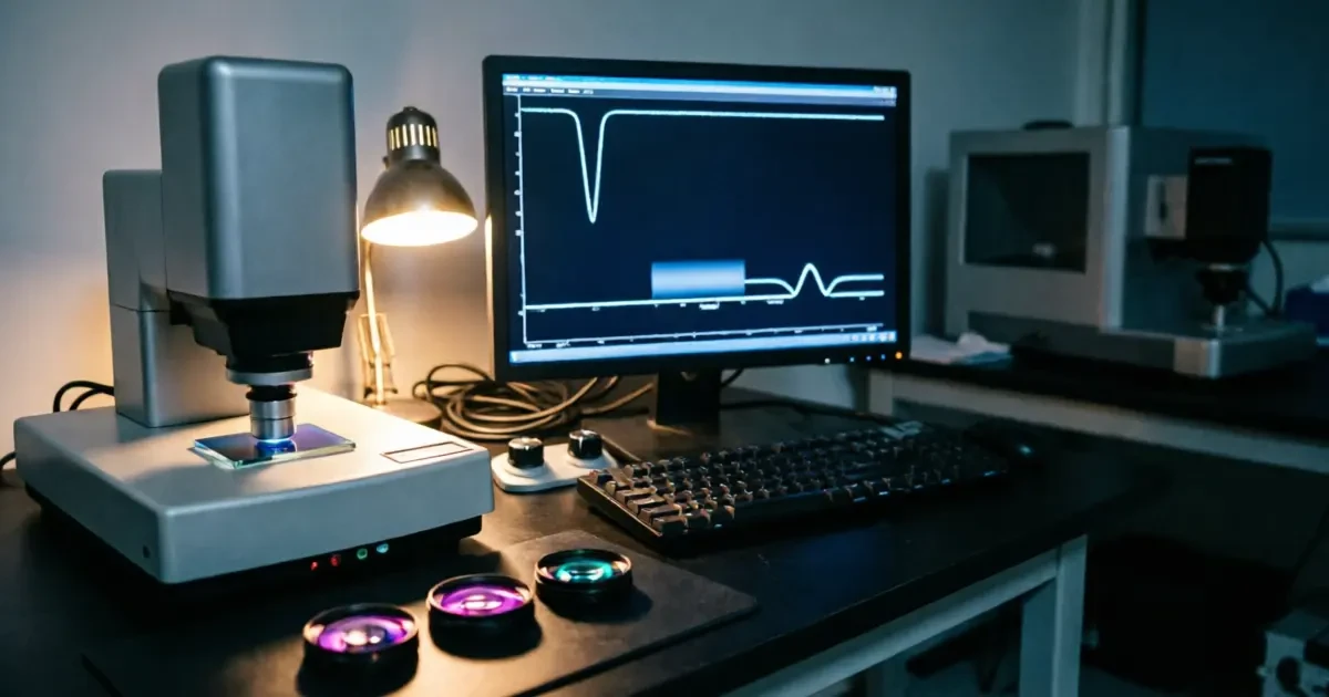
Spectral performance is measured on a spectrophotometer, and the report should state the measurement geometry, the polarisation, the spot size and the reference used. Reflectance measured at normal incidence will not predict performance at 45°, and a measurement spot that sits outside the clear aperture says nothing about the coated area that matters. Our coating line issues spectral test reports with the delivered parts, and the report identifies which surface and which witness sample was measured.
Two further checks matter for production: adhesion, verified by tape or abrasion methods agreed with the customer, and environmental stability, verified by humidity and temperature exposure. Both are process qualifications rather than per-part measurements, but a customer who never asks about them is relying on the supplier's internal qualification without knowing its scope.
Specification checklist
- Band: endpoints in nanometres, plus any bands that must be suppressed.
- Metric: average or maximum reflectance, per surface, at stated polarisation.
- Angle: design angle and permitted range.
- Substrate and surface: material, surface quality before coating, clear aperture.
- Durability: cleaning regime and environmental exposure.
- Verification: spectral report required, witness sample, measurement geometry.
A drawing carrying those six items returns a coating that can be qualified from the certificate. Anything less returns a coating that meets a number but may not meet the application — which is the origin of most coating disputes we are asked to resolve.
Need a coating design matched to your detector band? Send your drawing, specification or beam profile and our engineering team will review it and reply with a quotation.Request a coating quotation
Frequently Asked Questions
What reflectance can I expect from a standard broadband AR?
Our Precision grade holds R < 0.25% per surface across the specified band, and Commercial grade holds R < 1.5%. Tighter performance is available as a custom design, but it usually requires a narrower band or a fixed angle, and it should be discussed before the prescription is frozen.
Can the same coating cover both 532 nm and 1064 nm?
It can, but each line will perform worse than a dedicated design. Dual-line coatings typically reach around 0.5% at each line rather than the 0.2% a single-line design achieves. If one line is signal and the other is a pump or alignment beam, specify which line must be optimised.
Does coating change the substrate flatness?
Yes, by an amount that depends on stack thickness, stress and substrate stiffness. On thin windows and large apertures the effect can be a significant fraction of a wave. Where flatness or transmitted wavefront is specified, state whether the figure applies before or after coating so that the deposition can be tuned accordingly.
How do I specify a coating for a prism with three working faces?
Provide a per-face table: band, angle, reflectance target and whether the face is transmissive or reflective. Prism geometry means each face sees a different incidence angle, and a single blanket note will not control the faces that matter.
Is laser damage threshold part of a standard AR specification?
It is not, and it should be added explicitly for laser applications. Damage threshold depends on layer materials, deposition process, defects and pulse duration, so it must be quoted as a requirement with the laser parameters — wavelength, pulse length, repetition rate and fluence — rather than assumed from a catalogue figure.