CNC Polishing vs Diamond Turning vs Glass Molding: Choosing an Asphere Process
CNC polishing, diamond turning and glass molding reach different tolerances at different volumes. How to choose an asphere route from slope error, material and quantity.
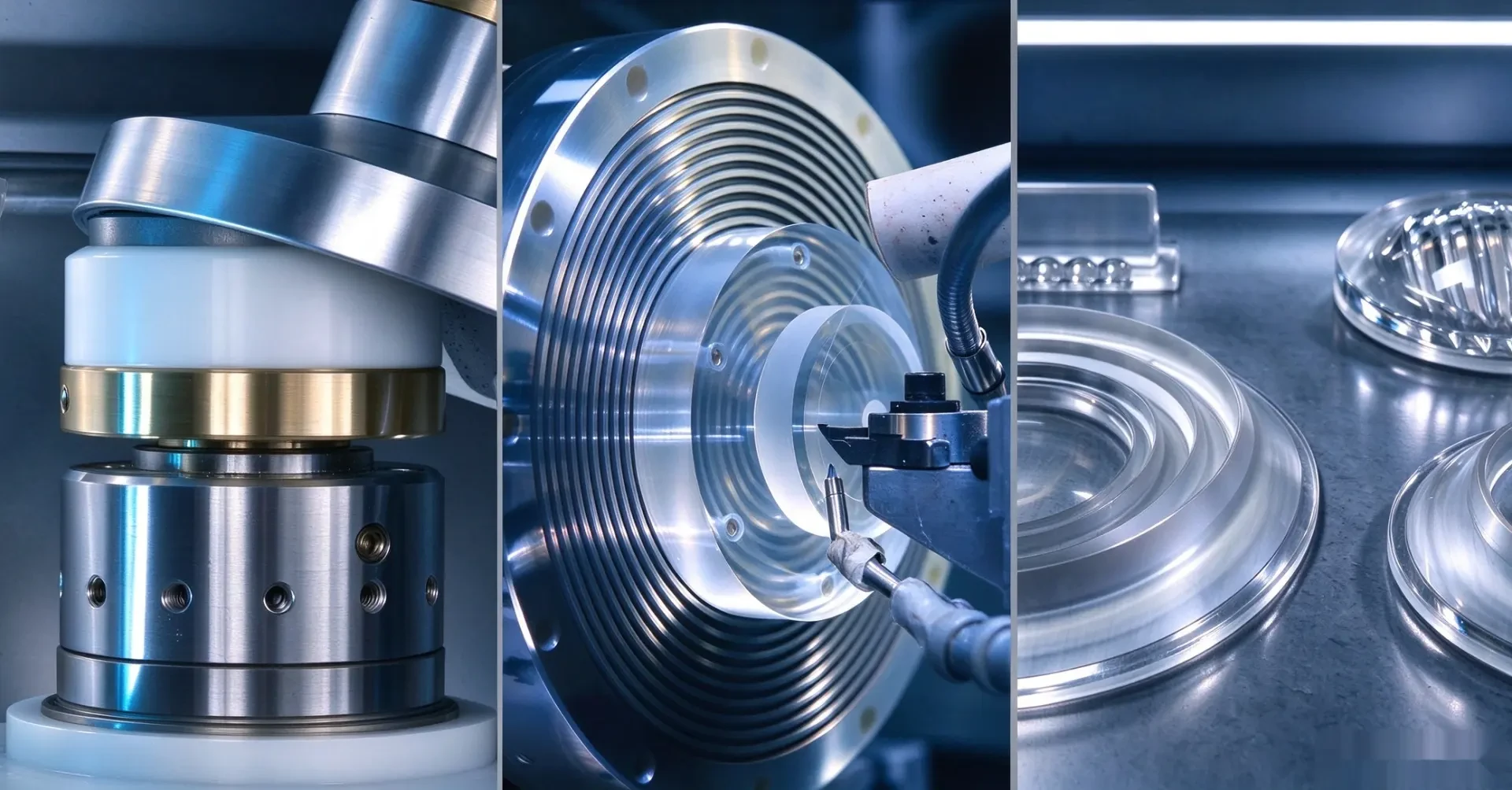
Aspheric surfaces earn their place by removing aberration that spherical surfaces cannot correct without extra elements. One asphere can replace two or three spherical elements, which reduces assembly count, stray-light surfaces and alignment sensitivity. The manufacturing question is not whether an asphere is better but which of three processes can deliver it at the tolerance and volume the programme needs — and each process has a distinct cost curve.
What the surface has to achieve
An asphere is described by a base radius, a conic constant and, where needed, polynomial terms. The conic alone covers the common cases: an ellipse for k between 0 and −1, a parabola at k = −1, a hyperbola below −1. In manufacturing terms the surface is defined by three measurable quantities: profile accuracy in micrometres, slope error in micrometres per millimetre, and surface form deviation in waves PV. Slope error is the one most often omitted and the one that most often predicts real performance, because a surface can sit inside a PV limit while its local slope scatters light outside the diffraction limit.
Our tolerance structure for aspheric lenses runs from 2.0 µm PV profile accuracy with 1.0 µm/mm slope error at Commercial grade, through 0.5 µm and 0.3 µm/mm at Precision, to 0.1 µm and 0.1 µm/mm at High Precision. Centration limits tighten in step, from 0.05 mm to 0.01 mm to 0.005 mm. Those numbers, not the process name, determine which route is viable.
CNC polishing: the precision route for glass
Computer-controlled polishing uses a small sub-aperture tool that follows a deterministic path, with dwell time or pressure modulated to converge on the target figure. It works on glass, handles steep departures from a sphere, and produces the best figure accuracy of the three routes — our polishing cell reaches 0.5 µm PV profile accuracy at Precision grade and 0.1 µm PV at High Precision, against surface form down to λ/20 PV and surface quality to 10/5.
The trade is time. Polishing is a serial process with iterative metrology between runs, so cost per part falls slowly with volume. It suits prototypes, small batches, large apertures and any application where the tolerance is the reason the asphere exists. It also suits freeform surfaces, which are polished on the same platform using the same sub-aperture approach — see the freeform optics range for the geometries involved.
Two constraints deserve early attention. Polishing struggles with surfaces that cannot be reached by the tool, so deep concave aspheres with small radii need a design review before quotation. And polishing generates subsurface damage if the grinding sequence is rushed, which shows up as scatter or as coating defects weeks later.
Single-point diamond turning: deterministic form on IR materials
Diamond turning machines the surface with a monocrystalline tool on an ultra-precision lathe, producing the figure directly from the tool path. Form accuracy reaches about 0.2 µm RMS with surface roughness down to Ra 1 nm in our cell, which is excellent for infrared optics where wavelength is long and scatter requirements are usually expressed in different terms.
Material compatibility is the limiting factor. Zinc selenide, zinc sulfide, germanium, silicon, chalcogenide glasses and polymers cut cleanly; ordinary optical glasses do not, because the tool wear rate is unacceptable at production volumes. For visible-light aspheres in glass, turning is normally used for prototypes and then transferred to polishing or molding for series production.
Turning leaves a directional tool texture. For imaging at 3–5 µm this is usually invisible; for a CO2 laser delivery optic at 10.6 µm it is irrelevant; for a visible prototype it can be polished out afterwards in a post-process. If your application is scatter-sensitive in the visible, declare it, because the finishing route changes.
Precision glass molding: the volume route
Glass molding presses a heated glass preform between two precision moulds, replicating the aspheric surface in a single cycle. Form accuracy is around 1 µm RMS, which suits consumer imaging, automotive sensors and laser diode collimation but not lithography-grade work. The economics invert: tooling is a fixed cost that must be amortised, so the process becomes attractive from roughly several thousand pieces upward and dominant at high volume.
Geometry constraints are real. Molding favours small apertures, rotationally symmetric surfaces and mouldable low-transition-temperature glasses. Large parts, high-index speciality glasses and aggressive aspect ratios either exceed press capability or shorten mould life. Mould life also sets the effective tolerance drift across a production run, so a programme that needs High Precision grade throughout is usually a polishing programme, not a molding one.
Route | Typical form | Materials | Economic volume | Best fit |
|---|---|---|---|---|
CNC polishing | 0.5 µm PV precision, 0.1 µm PV high precision | Most optical glasses and crystals | 1 to a few thousand | Precision and high-precision aspheres, large apertures, freeforms |
Diamond turning | ~0.2 µm RMS form, Ra 1 nm | ZnSe, ZnS, Ge, Si, chalcogenides, polymers | 1 to tens of thousands | IR optics, prototypes, freeform and non-rotational surfaces |
Glass molding | ~1 µm RMS form | Mouldable low-Tg glasses | Several thousand upward | Small-aperture volume aspheres |
Metrology decides whether the tolerance is credible
An asphere cannot be verified with a spherical interferometer, because the return wavefront does not match the reference. Two methods cover most work. A computer-generated hologram converts the interferometer into a null test matched to the aspheric departure, giving full-aperture phase data at high resolution; a profilometer traces a meridional profile and reports form and slope directly. The two are complementary: the CGH shows the whole surface, the profilometer shows the local slope behaviour that the CGH can smooth out.
For freeform and strong-departure surfaces, sub-aperture stitching assembles overlapping measurements into a full-aperture map. Each method has its own uncertainty, and the report should state the method, the wavelength and the aperture measured. Our manufacturing flow issues surface accuracy reports that name the technique, because a λ/20 claim without a stated method is not a specification.
Choosing a route
Start from the surface definition and the critical tolerance — slope error and centration usually decide more than PV.
Check material against process: glass points to polishing or molding, IR crystals point to turning.
Check geometry: aperture, departure from best-fit sphere, accessibility for the polishing tool.
Estimate volume: below a few hundred pieces, tooling-heavy routes rarely pay back.
Confirm the metrology route before releasing the drawing; if the surface cannot be measured, it cannot be accepted.
Programmes that span prototype and production often use a hybrid path: turned or polished prototypes to prove the design, then molding for volume once the prescription is frozen. That sequencing keeps schedule risk low, and it is the pattern we normally recommend for OEM/ODM programmes that begin with a handful of samples.
Planning an aspheric programme and unsure of the route? Send your drawing, specification or beam profile and our engineering team will review it and reply with a quotation.Discuss your asphere project
Frequently Asked Questions
Can any glass asphere be molded?
No. Molding requires low-transition-temperature glasses that flow without crystallising, and the mould material must survive repeated thermal cycling. High-index speciality glasses, large apertures and aggressive surface departures usually stay on the polishing route.
Why is slope error specified separately from PV?
Because they describe different failures. PV measures the peak-to-valley departure across the aperture, while slope error measures how fast the surface changes locally. A surface can meet a PV limit and still scatter light if the slope exceeds the design assumption, particularly in laser and imaging systems with tight point-spread requirements.
What is the smallest quantity you can supply for a polished asphere?
Single pieces, and prototypes typically ship in 2–3 weeks depending on coating and metrology requirements. The cost per piece is dominated by set-up and iterative figuring, so the second and third units are much cheaper than the first.
Can diamond-turned surfaces be used in the visible?
They can, for prototyping, and they can be post-polished if the tool texture is unacceptable. In production, visible-light glass aspheres are normally polished or molded, because tool wear and texture make turning uneconomic at short wavelengths.
How do you verify an asphere before shipping?
With a CGH null test for full-aperture form and a profilometer trace for slope and local figure, plus a centration measurement on the finished element. The inspection report states which method produced which number, together with the measurement wavelength and aperture.