Building an Optical Tolerance Budget That Survives Production
How to turn a wavefront target into manufacturing limits: surface-versus-wavefront conversion, sensitivity allocation, RSS versus worst case, and compensators.
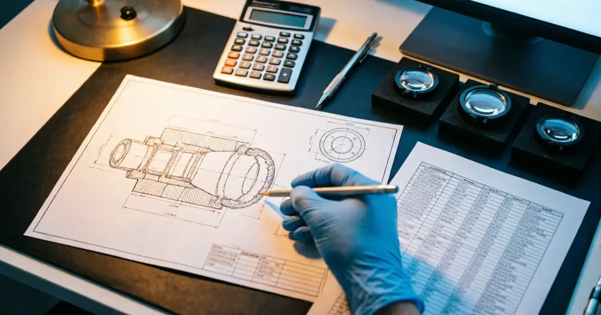
A tolerance budget converts an optical performance target into manufacturing limits that a shop can hold and a quality engineer can measure. Without one, designs pass in simulation and fail at first article, and the failure is usually attributed to the supplier rather than to the allocation. The method below is the one we apply when reviewing a design-for-manufacture package, and it works equally well for a single lens and for a multi-element assembly.
Start from a measurable performance target
The budget needs a number to protect. "Good imaging" is not a target; "wavefront error below λ/4 RMS over the full field" is. Typical targets are wavefront error at a stated wavelength and field, modulation transfer function at a stated spatial frequency, boresight or beam-pointing error in arcseconds, or focal shift across a temperature range. Choose one primary metric and at most two secondary ones — a budget that tries to protect five metrics simultaneously usually protects none of them.
State the wavelength at which the target is defined. A λ/4 requirement at 633 nm is 158 nm of wavefront; the same λ/4 at 1064 nm is 266 nm. Mixing wavelengths between design and inspection is one of the most common sources of first-article disagreement.
Convert wavefront to surface correctly
Manufacturing limits are surface limits, while design targets are wavefront limits, and the conversion factor depends on how the element is used. In reflection, a surface error of h produces 2h of wavefront error because the beam traverses the deviation twice. In refraction, the same surface error produces approximately 2(n − 1)h. For BK7 at n = 1.517 that is about 1.03h per surface — close to unity, which is why a transmitted-wavefront budget and a surface budget are often confused. For high-index materials such as germanium at n = 4, the factor rises to about 6h, and a surface tolerance copied from a visible design will be badly wrong.
Write the conversion into the budget document. It takes one line and it prevents an entire class of argument at first article.
Allocate by sensitivity, not by round numbers
Sensitivity analysis tells you how much each parameter moves the performance metric. A typical singlet — a plano-convex or meniscus element of the kind covered by our spherical lens range — has sensitivity to radius, thickness, irregularity, wedge and centration that differ by an order of magnitude. Allocating equal tolerances to each parameter is the most expensive possible choice, because the insensitive parameters are then over-specified for no benefit.
A practical workflow is to run a reverse sensitivity — perturb each parameter until the performance metric degrades by its allocated share — and take the resulting values as starting tolerances. Then round them to the nearest grade in the tolerance chart, which maps the three production grades against every parameter we manufacture to. Rounding to a grade rather than inventing a value keeps the drawing inside a proven process window.
| Parameter | Commercial | Precision | High Precision |
|---|---|---|---|
| Diameter | +0.00/−0.10 mm | +0.00/−0.025 mm | +0.00/−0.010 mm |
| Center thickness | ±0.15 mm | ±0.05 mm | ±0.02 mm |
| Irregularity (spherical) | 1.0 wave PV | 0.25 wave PV | 0.05 wave PV |
| Wedge / edge thickness difference | 0.05 mm | 0.01 mm | 0.005 mm |
| Scratch-dig | 40/20 | 20/10 | 10/5 |
Combine contributions deliberately
Two methods dominate. Worst-case addition sums the absolute contributions and is conservative: it assumes every element is at its limit in the same direction at the same time. Root-sum-square assumes the errors are independent and random, and returns a smaller total that is realistic for volume production but optimistic for a single assembly.
Use RSS when the errors genuinely arise from independent causes and the yield question is statistical. Use worst-case when the requirement is a hard system limit — a boresight that must not exceed a specification on any unit, a safety-critical wavefront, a measurement instrument that must be calibrated against its own certificate. Where a design sits close to the boundary, the honest approach is to run both and quote the range.
Do not forget the terms that are not on the optical drawing. Mounting stress, cementing shrinkage, coating stress and thermal gradients all consume budget, and they are frequently the terms that break a design that was tight in simulation. A cemented doublet whose elements are each within tolerance can still fail if the bond line is uneven, because the cementing process introduces wedge that no single-element drawing controls.
Decide what can be compensated
A compensator absorbs part of the error stack, which relaxes the individual tolerances. Focus adjustment is the classic example: if the mount allows axial positioning during alignment, thickness and radius errors partly collapse into a focus shift that the adjuster removes. The budget should separate compensated from uncompensated contributions and allocate only to the latter.
Compensators cost money in assembly, though, and they cost time in production. A design that relies on three adjustments may be cheaper to manufacture and more expensive to build. The choice between tight tolerances and active adjustment is a programme decision, and it should be made explicitly rather than discovered when the first units fail to converge.
Price the tightening
Cost does not scale linearly with tolerance. Moving from Commercial to Precision on diameter and thickness is routine; moving to High Precision on irregularity, wedge and centration simultaneously changes the process, the inspection time and the yield. The usual pattern is a step change at each grade boundary, plus a further step when a parameter moves outside the standard grade and needs a bespoke process.
A budget that identifies the two or three parameters actually consuming performance allows the rest to be loosened. In our experience, the majority of over-specified drawings tighten everything because the designer could not identify which parameter mattered — and the cost of that uncertainty is carried by the programme for its whole life.
Close the loop with verification
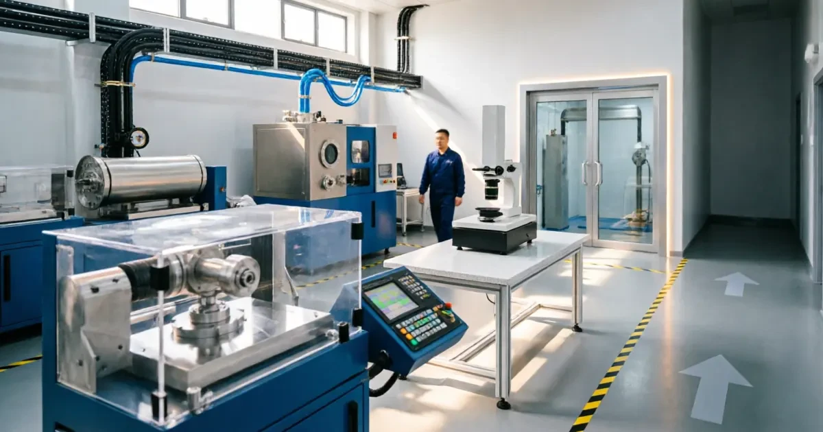
The budget is only real if the inspection plan measures the same quantities. Confirm that the chosen limits can be measured: irregularity needs an interferometer at the design wavelength, wedge needs a centration or thickness measurement, angle needs an autocollimator. Where a parameter cannot be measured at the supplier, it cannot be accepted or rejected with evidence, and the requirement becomes a discussion rather than a specification. Every grade we quote is backed by an instrument in our own metrology cell, which is why the limits in the chart can be verified against delivered parts rather than asserted on a certificate.
Our design services team runs the sensitivity analysis and the tolerance allocation as a standard part of the design-for-manufacture review, and returns a budget document that maps each parameter to a grade and to an inspection method. For assemblies, the same exercise is applied to the stack rather than to single elements, since that is where the uncompensated error usually accumulates.
Want a tolerance budget checked against real process capability? Send your drawing, specification or beam profile and our engineering team will review it and reply with a quotation.Request a tolerance review
Frequently Asked Questions
Should an optical tolerance budget use RSS or worst-case addition?
RSS is appropriate when errors are independent and the acceptance question is statistical, which describes most volume production. Worst-case is appropriate for hard system limits, single-unit qualification and safety-related requirements. Where the margin is thin, calculate both and report the range rather than selecting the more favourable answer.
How much wavefront error does a surface error produce?
In reflection, twice the surface deviation; in transmission, approximately 2(n − 1) times the surface deviation. For BK7 the transmission factor is close to 1, for germanium it is close to 6. Applying the wrong factor is a common cause of a budget that looks comfortable and fails at first article.
Can alignment absorb tolerance errors?
Partly. Focus and tilt adjustment can absorb a meaningful share of axial and angular error, which is why compensated and uncompensated terms are separated in the budget. Adjustment does not absorb irregularity, surface quality or coating variation, and it adds assembly cost and cycle time.
Why does tightening one parameter cost so much?
Because it usually crosses a process boundary rather than a numerical one. A tighter irregularity may require a different polishing sequence and more metrology iterations; a tighter wedge may require re-centring after cementing. The cost is in the process change, not in the number.
How do I know my tolerance is achievable before I release the drawing?
Compare each parameter against a proven grade in the published tolerance chart, and confirm the inspection method for any parameter that sits outside a standard grade. If a parameter has no measurement route at the supplier, the requirement is not yet a specification.