Interferometry, Profilometry, and CGH: Metrology for Precision Optics
What interferometry, CGH null tests, profilometry, autocollimators and spectrophotometers each report, and why two suppliers can disagree about the same part.
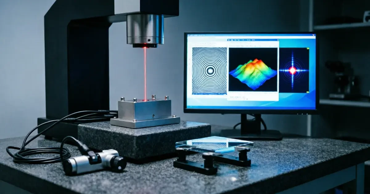
A specification only means what the measurement can support. Two suppliers can both claim λ/20 PV and deliver parts that behave differently, because the claim depends on the instrument, the wavelength, the aperture measured and the mounting used during test. Understanding what each instrument actually reports is therefore part of writing a specification, not an afterthought to it.
Interferometry: form and transmitted wavefront
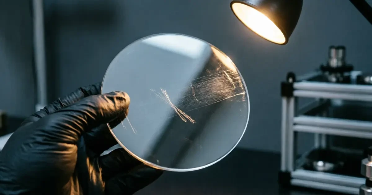
A laser interferometer compares the test surface against a reference wavefront and maps the deviation across the aperture. At 633 nm, λ/20 PV corresponds to about 31.6 nm, and λ/4 corresponds to 158 nm, so the numbers in a tolerance table are small in absolute terms and demand a controlled environment. Air turbulence, vibration and thermal drift all enter the measurement, which is why a stable bench and a settling period are part of the method rather than a convenience.
Interferometry reports surface form for a reflective surface and transmitted wavefront for a transmissive element. The two are not interchangeable: a lens measured in transmission includes both surfaces and the homogeneity of the substrate, so a transmitted-wavefront figure is always a system figure rather than a single-surface figure. When a drawing specifies surface irregularity per surface, the inspection must isolate that surface, usually by measuring against a reference flat or by using a reflection configuration.
Our flat optics work shows why the distinction matters. A window can have excellent surface flatness on each face and still fail a transmitted-wavefront requirement, because parallelism and homogeneity contribute independently.
Computer-generated holograms for aspheres
A spherical reference wavefront cannot null an aspheric surface, so the interferometer is fitted with a computer-generated hologram that shapes the test wavefront to match the nominal asphere. The result is a full-aperture phase map at high resolution, with the departure from nominal reported directly.
CGH testing is powerful but it is a null test: it tells you how far the surface is from the design, not whether the design is right. A CGH fabricated to the wrong nominal produces a clean map of the wrong surface, and the error propagates into every part measured against it. This is why the CGH design and its verification are part of the metrology chain, and why the report should identify the CGH used. For the geometries involved, see the aspheric lens range.
Profilometry: slope, texture and roughness
A profilometer measures a line across the surface rather than an area. A stylus instrument with a micrometre-scale tip traces the profile and reports form, waviness and roughness; a white-light interferometric profilometer measures an area at sub-nanometre height resolution over a small field. Both are used on aspheres and freeforms, where the local slope behaviour matters as much as the overall figure.
Roughness is quoted in ångströms RMS in our tolerance structure: 20 Å at Commercial grade, 10 Å at Precision and 5 Å at High Precision. For context, 5 Å is 0.5 nm RMS, which is a polished optical surface and requires the measurement itself to be clean, isolated from vibration and corrected for the instrument's own noise floor. Roughness drives scatter, so it matters most in high-power laser systems, in low-light imaging and anywhere a stray-light budget is tight.
Autocollimators and centration testers: the angular quantities
Angle tolerances are stated in arcminutes and arcseconds, and they need instruments that resolve them. A precision autocollimator measures angular deviation of a reflected beam with sub-arcsecond resolution, which is how prism angle accuracy — ±3–5 arcmin at Commercial grade, ±30 arcsec at Precision and ±5 arcsec at High Precision — is verified. The same instrument checks parallelism on flats, where the grade runs from 3 arcmin to 0.5 arcmin.
Centration is measured separately, usually by rotating the element and observing the reflected spot or the transmitted image. A centration tester resolves decenter to a few micrometres, which is what the 0.005 mm limit on high-precision aspheres requires. Note that centration of a finished element is not the same as wedge on the blank: cementing and mounting can introduce decenter after the individual surfaces have passed.
Spectrophotometry: the coating measurement
Coating performance is verified on a spectrophotometer, and the useful report states the wavelength range, the angle of incidence, the polarisation and the spot location. A reflectance curve measured at normal incidence does not predict performance at 45°, and a measurement taken outside the clear aperture says nothing about the coated area that matters.
Where the part is too large or too curved for the instrument's sample compartment, a witness sample coated in the same run is used. That substitution is standard practice, but it should be stated on the report, because a witness sample assumes the run was uniform — an assumption that holds for well-controlled processes and fails at the edge of a chamber.
Why two suppliers disagree about the same part
Most measurement disagreements come from four causes. The aperture measured differs: one supplier reports the full clear aperture, the other a central 80% zone. The wavelength differs: λ/4 at 633 nm and λ/4 at 1064 nm are different physical limits. The mounting differs: a part clamped in a fixture carries stress that a free-standing measurement does not. And the analysis differs: PV is sensitive to a single outlier pixel, while RMS or a Zernike fit is not, so the same map can produce very different numbers depending on the reported metric.
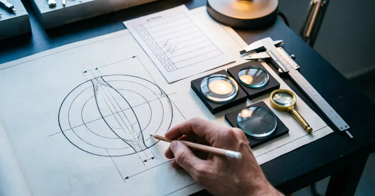
The remedy is procedural rather than technical. State the metric, the wavelength, the aperture and the mounting on the drawing; ask the supplier to report against those conditions; and, where a part is marginal, exchange the raw phase map rather than the summary figure. Our metrology group issues surface accuracy reports, angle reports and spectral scans with the delivered parts, and can supply the underlying data when a customer needs to reconcile results.
Matching instrument to requirement
| Requirement | Instrument | What it reports |
|---|---|---|
| Surface form, flats and spheres | Laser interferometer | PV and RMS deviation at the test wavelength |
| Aspheric form | Interferometer with CGH | Departure from nominal across full aperture |
| Slope and roughness | Stylus or white-light profilometer | Profile, local slope, Ra and RMS roughness |
| Prism and wedge angles | Precision autocollimator | Angular deviation in arcseconds |
| Centration | Centration tester | Decenter in micrometres |
| Coating reflectance | Spectrophotometer | Spectral reflectance at stated angle and polarisation |
Each of these maps to a line in the tolerance chart, and the chart is only meaningful because every line has a measurement route behind it. When a requirement cannot be measured, the correct response is to redesign the requirement rather than to accept an unverifiable claim.
Need measurement data that matches your acceptance criteria? Send your drawing, specification or beam profile and our engineering team will review it and reply with a quotation.Ask about inspection reports
Frequently Asked Questions
What does λ/20 PV mean in nanometres?
At the 633 nm helium-neon wavelength, λ/20 is about 31.6 nm peak-to-valley. The same fraction at 1064 nm is about 53 nm, so a specification should always state the wavelength at which it applies.
Why is RMS reported as well as PV?
PV is dominated by a single high or low point and can be driven by a dust particle or a handling mark. RMS describes the overall distribution and correlates better with imaging performance. Reporting both, with the same map, gives a fuller picture than either alone.
Can you measure a coated part interferometrically?
Yes for surface form, using the coated surface as the reflective reference, though a highly reflective coating can saturate the detector and requires attenuation. Transmitted wavefront through a coated element is also measured, and it includes coating stress effects on the substrate figure.
Do you supply raw measurement data?
Yes, on request. Summary reports are issued as standard; where a customer needs to reconcile results with their own inspection, we can provide the phase maps or profilometer traces for the parts in question.
How is roughness measured on a curved surface?
With a small-field profilometer positioned on the region of interest, or with a stylus trace along a meridional line. Because the measurement covers a small area, the reported roughness characterises that area rather than the whole surface, and the report should identify where the measurement was taken.