Freeform Optics for Laser Beam Shaping: Design and Manufacturing Notes
Freeform surfaces buy a shorter optical train for beam shaping, at the price of stricter datum, slope and metrology discipline. What to define before quoting.
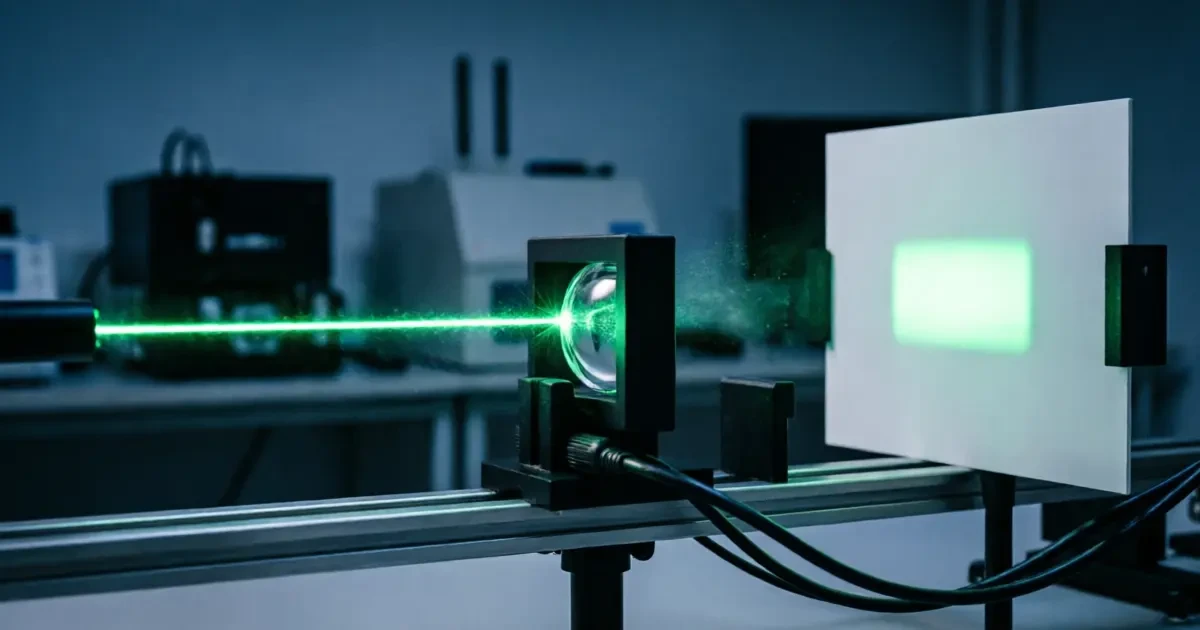
Beam shaping is one of the few optical problems where a freeform surface is usually the cheaper answer, not the more exotic one. A multi-element spherical system that converts a Gaussian beam into a flat-top line, or a diode bar into a uniform illumination field, needs several elements, careful spacing and an alignment budget. A single freeform surface can perform the same mapping, provided the surface is defined, manufactured and mounted with the right discipline.
What a freeform surface buys
A freeform is any surface that is neither rotationally symmetric nor describable by a simple conic. In beam shaping, the surface redistributes intensity by controlling local slope: steeper regions spread energy over a larger target area, flatter regions concentrate it. Because slope is the design variable, the surface can implement a mapping that spherical optics would need several elements to approximate.
The practical consequences are a shorter optical train, fewer air-glass interfaces and therefore lower loss and fewer ghost reflections, and a smaller alignment stack. The cost is that the surface cannot be verified with a spherical test, the alignment degrees of freedom increase, and the design must be specified as a mathematical surface rather than as a radius and a thickness.
Where freeforms fit
Three application families dominate. Laser processing uses freeforms to convert a Gaussian into a uniform line or a rectangular top-hat for cutting, welding and surface treatment. Illumination uses them to shape an LED or laser source into a defined field with controlled cut-off, which is common in machine vision and automotive sensing. And imaging and sensing systems use them to correct aberrations that would otherwise need extra elements, particularly where package volume is constrained. Our industry pages cover the application context for each.
Each family imposes a different requirement. Laser shaping is slope-critical and often polarisation-sensitive; illumination is efficiency-critical and tolerant of figure error that does not affect the mapping; imaging is wavefront-critical and usually needs the tightest form tolerance of the three. It is worth stating which family your application belongs to, because the answer changes both the tolerance allocation and the acceptance test at delivery.
Define the surface, not just the effect
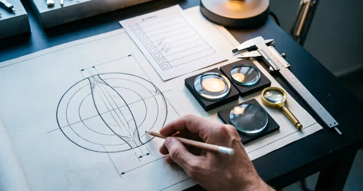
A freeform drawing must carry a mathematical definition: the surface type (polynomial, Zernike, radial basis function or spline), the coefficient set, the aperture boundary and the coordinate system, including datums. Without the datums, the surface cannot be positioned, and a repositioning error of 0.01 mm in a beam-shaping element can move the output pattern by more than a millimetre at the target.
Our tolerance structure for freeform optics runs from 5.0 µm PV profile accuracy with 0.05 mm position tolerance at Commercial grade, through 1.0 µm and 0.01 mm at Precision, to 0.2 µm and 0.005 mm at High Precision. Those are surface and position limits; they do not by themselves guarantee the output pattern, so the design file should also state the predicted performance so that the manufactured part can be compared against intent.
Manufacturing routes and their limits
Two routes cover most freeform work. Single-point diamond turning machines the surface deterministically on a five-axis ultra-precision lathe and is the standard route for infrared crystals and polymers, reaching form accuracy around 0.2 µm RMS with roughness to Ra 1 nm. CNC sub-aperture polishing handles glass freeforms, using a small tool that follows the surface with dwell-time control to converge on the figure.
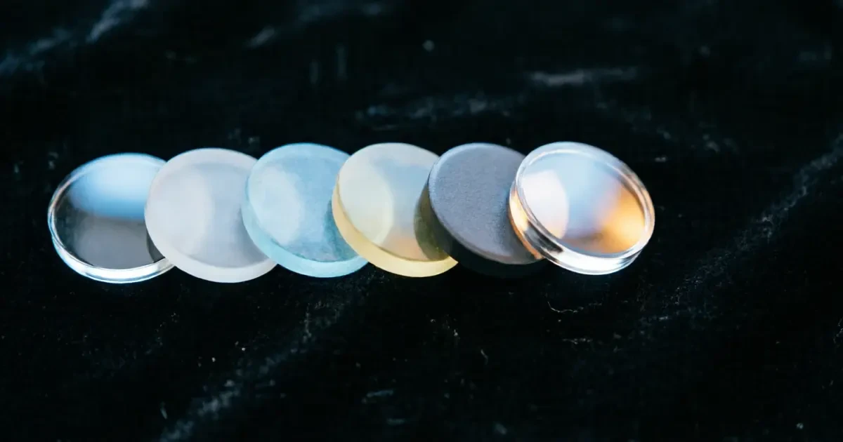
The choice follows material more than geometry. Turnable materials — ZnSe, ZnS, germanium, silicon, chalcogenides, PMMA and COC — go to turning; polishable glasses such as BK7 and fused silica go to polishing. Scale matters as well: turning is economic from single pieces upward, while polishing has a longer set-up path but reaches the tighter tolerances that visible-light imaging demands. The manufacturing overview describes the process cells, including the polishing cell that reaches λ/20 PV surface form.
One geometric constraint is worth checking early: a freeform with steep local slopes may be unreachable by the polishing tool, and a turned surface may show tool marks where the slope changes rapidly. A surface that is manufacturable in principle can still be untestable, which is the subject of the next section.
Metrology is the binding constraint
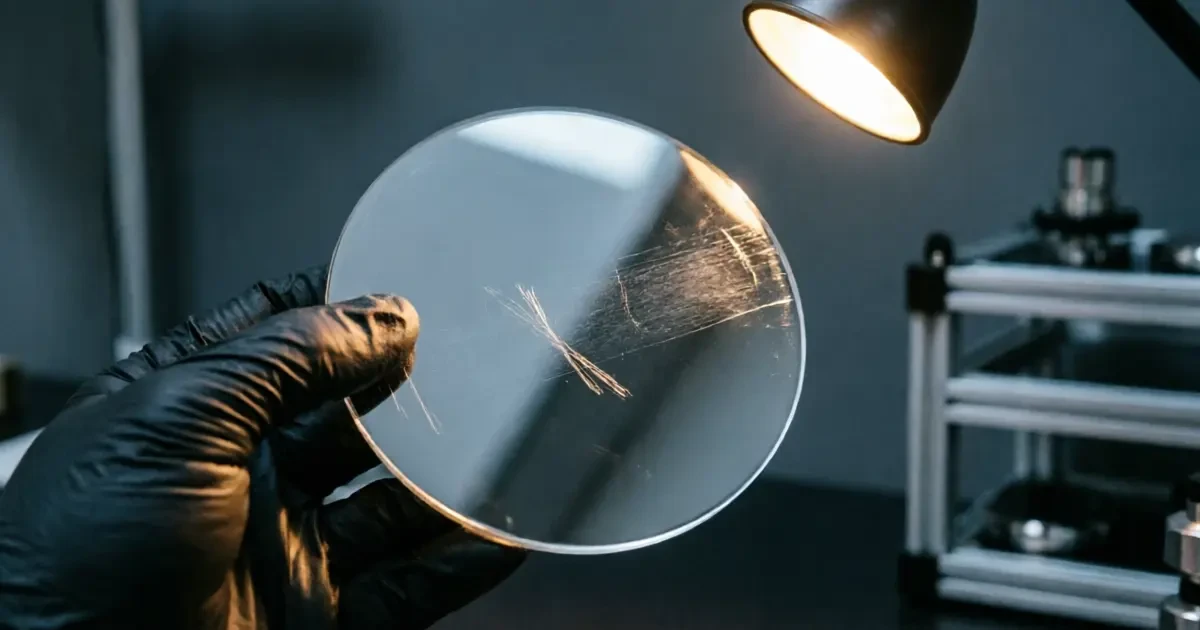
A spherical interferometer cannot null a freeform, and a CGH null is expensive for a one-off surface because the hologram must be designed and fabricated for that specific departure. In practice, freeform metrology combines a profilometer trace along one or more meridians with a sub-aperture stitching map, or uses a scanning white-light instrument over a limited field. The result is a set of overlapping measurements rather than one full-aperture map, and the uncertainty of the assembly must be understood before the tolerance is committed.
This is why we ask for the surface definition and the intended application before quoting a freeform tolerance. A slope-critical laser application and a figure-critical imaging application can look identical on a drawing while needing different measurement strategies and different acceptance limits.
Alignment and integration
Freeform elements usually carry more alignment sensitivity than their spherical equivalents, because the surface no longer has rotational symmetry to fall back on. Three practices reduce the risk. First, define datums on the element itself so that the mount can locate the surface without relying on its optical axis. Second, include a mechanical feature — a flat, a notch or a mounting flange — that fixes rotation. Third, design an alignment procedure into the assembly, with a measurable output such as the beam profile at the target plane, rather than assuming that mechanical location is sufficient.
Where the programme allows, a design-for-manufacture review before the drawing is released is the cheapest risk reduction available. Our design services team reviews freeform definitions against manufacturability and metrology capability, and returns comments on datum strategy, slope limits and tolerance allocation before tooling is committed.
Have a beam-shaping requirement to evaluate? Send your drawing, specification or beam profile and our engineering team will review it and reply with a quotation.Send us your beam profile target
Frequently Asked Questions
When is a freeform cheaper than a multi-element spherical design?
When the system needs a non-rotationally symmetric mapping, a compact package, or fewer surfaces for loss and ghost control. If a two-element spherical design already meets the requirement, it is usually the lower-risk choice because its metrology and alignment are standard.
What tolerance is realistic for a glass freeform?
Precision grade at 1.0 µm PV profile accuracy and 0.01 mm position tolerance covers most illumination and beam-shaping work. High Precision at 0.2 µm and 0.005 mm is available, but it demands a matched metrology strategy and a datum scheme agreed before manufacture.
Can freeform surfaces be coated?
Yes, with the caveat that coating uniformity depends on the angle of incidence across the surface, which varies on a freeform. Where reflectance uniformity matters, the coating design must account for the surface geometry rather than assuming normal incidence everywhere.
How do you verify that the beam profile is correct?
By measuring the output as well as the surface. Surface metrology confirms the figure; a beam profile measurement at the target plane confirms that the mapping works. Both are needed, because a surface within tolerance can still produce an unexpected profile if the element is positioned incorrectly.
Which materials are available for freeform optics?
Diamond-turnable materials include ZnSe, ZnS, silicon, germanium, chalcogenide glasses, PMMA and COC. Polishable glass freeforms are made in BK7, UV fused silica and other optical glasses. The material choice usually follows the wavelength band and the manufacturing route together.